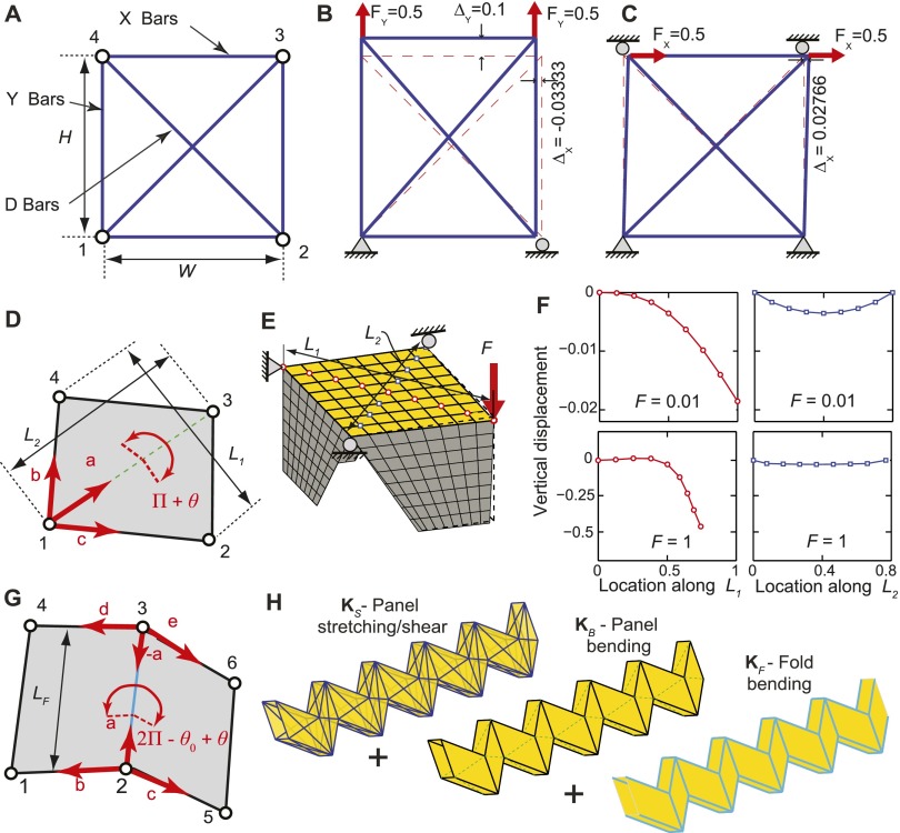
Fig. S1.
Schematics and tests of the bar and hinge model. (A) Schematic of indeterminate bar frame for simulating in-plane panel stretching and shearing. (B) Tensile patch test of bar frame exhibiting isotropic behavior. (C) Shear patch test of bar frame. (D) Schematic orientation of rotational hinge simulating panel bending along the diagonal . (E) FE model used to study bending of thin sheet restrained at edges by orthogonally placed thin sheets. (F) Curvature along the diagonals of the FE model for a small displacement () and a large displacement () case. (G) Schematic of the two rotational hinges used to simulate bending along a prescribed fold line of length . (H) The three components of the bar and hinge model shown on the single tube.

