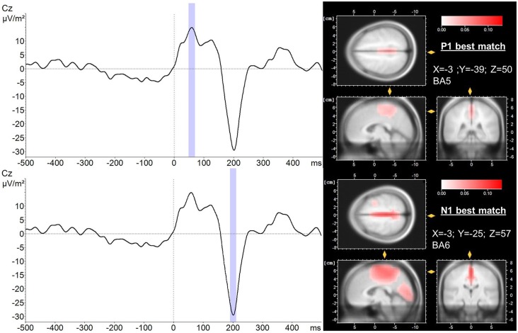
Figure 4.
LORETA localization (right) of the P1 (upper trace) and N1 (lower trace) potential averaged over trials and subjects (left). A 20 ms peri-peak window was considered for LORETA transformation (blue). LORETA anatomy slides are based on the MNI305 template and locked to the localization of maximal current density during the P1 and N1 potential, respectively. In addition, the coordinates of the voxel reflecting maximal current density (best match) and the corresponding Brodmann area (BA) are presented. Time 0 indicates perturbation onset.

