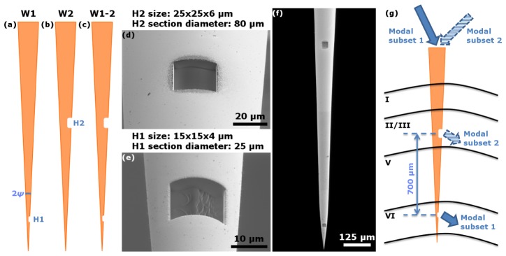
Fig. 1.

(a)-(c): Schematic representation of the devices with one (a, b) and two (c) windows used for the experiments. (d), (e): Scanning electron microscope images showing in detail the optical windows milled on device W2 (d) and W1 (e). (f): Scanning electron microscope image of a typical two-window MPEF. (g): Schematic representation of a two-window MPEF implanted in the mouse primary motor cortex.
