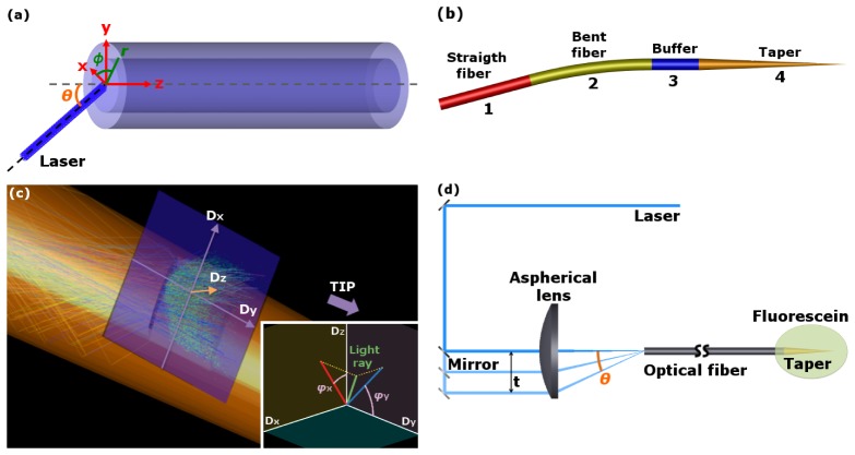
Fig. 2.
(a): Definitions and coordinates system at the input face of the optical fiber. (b): Three-dimensional schematic layout of the ray tracing model in which the four blocks are indicated: a straight optical fiber (1), a bent optical fiber (2), the buffer region (3) and the tapered region (4). (c) Detail of the position of the detector recording the geometrical properties of the rays outcoupled by the windows. The inset shows the rays outcoupling angles φx and φy recorded by the detector. φx is the angle between Dz and the projection of the outcoupled ray propagation direction on the plane Dz-Dx. φy is the angle between Dy and the projection of the outcoupled ray propagation direction on the plane Dz-Dy. (d) Experimental setup used to select the coupling angle between the laser beam and the input facet of the optical fiber.

