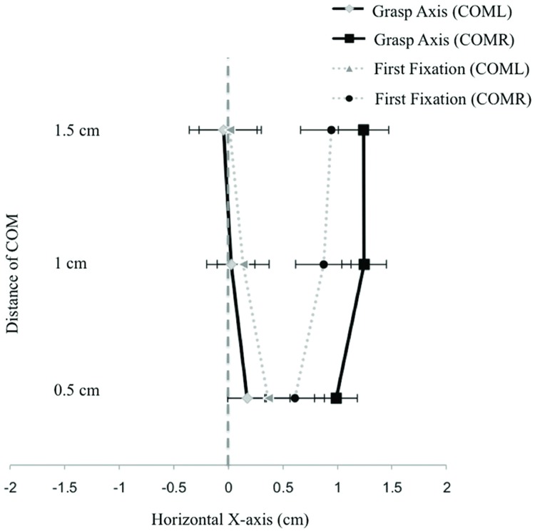
FIGURE 6.
Displays first fixation positions and grasp axis locations across the three COM distances (collapsed across object) for both leftward and rightward oriented COMs in Experiment 2. Negative values represent positions that are located to the left of the object’s horizontal midline. Error bars represent the standard error of the mean.

