
Figure 3.
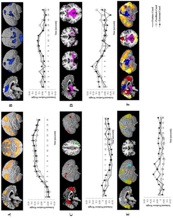
Components identified in the Switch Condition fMRI-CPCA analysis, in which variance was constrained by switching cue condition. Regions within each component are illustrated as a colored overlay on the MNI brain template in MRIcron. Components 1 (A), 2 (B), and 4 (D) had only positive loadings. In Component 3 (C), positive loadings are shown in red and negative in green; in Component 5 (E) positive loadings are shown in yellow and negative in blue. Graphs for each component show the estimated hemodynamic response across all voxels with positive loadings within the component for each condition across the first 16 seconds of each rule learning problem, beginning with the switch trial. Error bars show standard error. Bottom right (F) images show all components overlaid on the same rendered brain for comparison purposes. Colors follow those used in each individual component images.