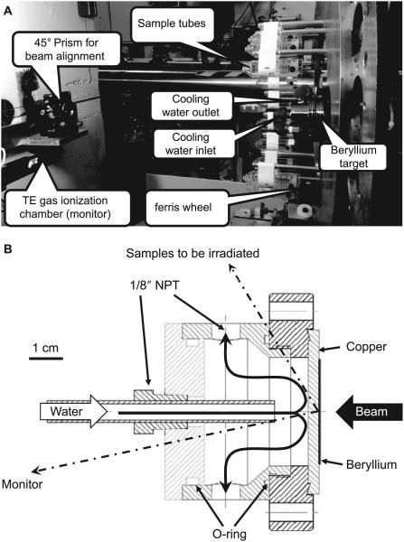
FIG. 2.
Panel A: Photo of the irradiation facility. Beam arrives from the right and impinges on the beryllium target generating neutrons. Samples to be irradiated (blood or mice) are placed in sample holders (shown here empty) and mounted on a Ferris wheel rotating around the target-cooling chamber. At the left is the tissue-equivalent gas ionization chamber used as a beam monitor and the right angle prism used for aligning the beam line. Panel B: Cross section of target and cooling chamber. Direction to the center of the sample holders (190 mm away) and the monitor chamber (610 mm away) are shown.

