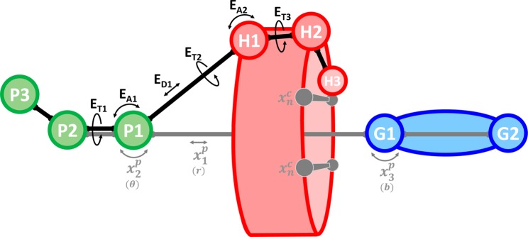
Figure 3.

Restraint scheme demonstrating the use of anchor particles for attach–pull–release (APR) free energy calculations. P1–3 are anchor particles, H1–3 are host atoms, and G1–2 are guest atoms. The ED1, EA1–2, and ET1–3 labels indicate distance, angle, and torsion restraints, respectively, which modify only the host translational and rotational degrees of freedom and are included implicitly in the potential energy function, E(X), as described in the main text. These restraints are held constant throughout all simulation windows and do not perturb the host’s conformational degrees of freedom. Indicated in gray with labels x1p, x2, x3p, and xn are restraints that are attached over a series of simulation windows and are subsequently used to pull the guest out of the host cavity. In this example, x1p is a distance restraint, x2 and x3p are angle restraints, and xn represents host conformational restraints (of any harmonic form). In parentheses, the corresponding spherical coordinate or Euler angle is indicated for each translational/rotational pose restraint, as defined in the main text. See Figure S1 for a full illustration of the APR process.
