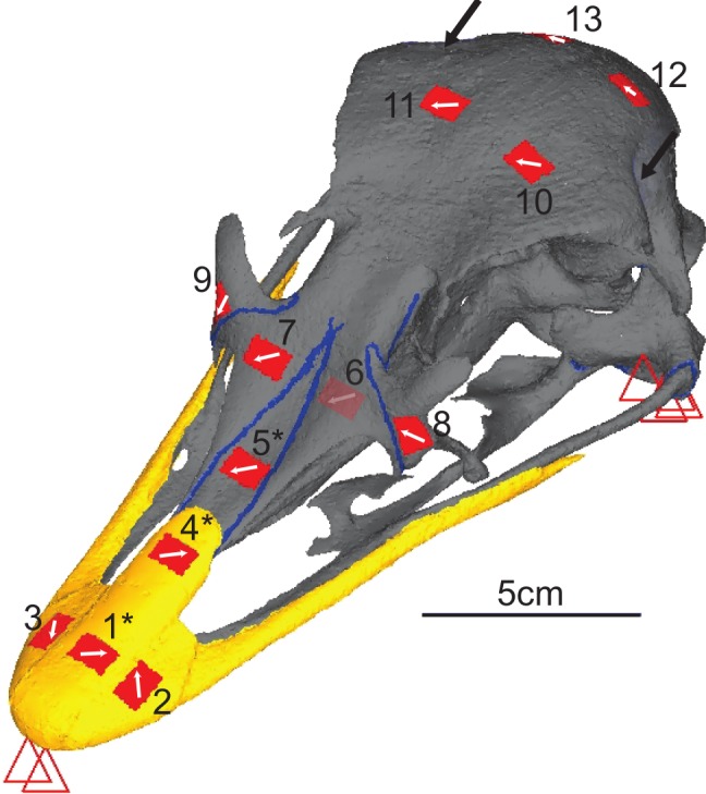
Figure 3. Digital reconstruction of the ostrich skull.

Red triangles represent the constraints, black arrows show orientation and location of loads, red rectangles are membrane elements that mirror the strain gauges. Gauge 6 was non-functional so was not included in the model, but its location is marked. The blue lines are sutures, and the yellow material is the keratinous rhamphotheca. The trabecular bone is not visible. Gauges labelled with an asterisk (*) are sites where nanoindentation was performed. Direction from grid one is labelled as the white arrow from which strain orientation were measured.
