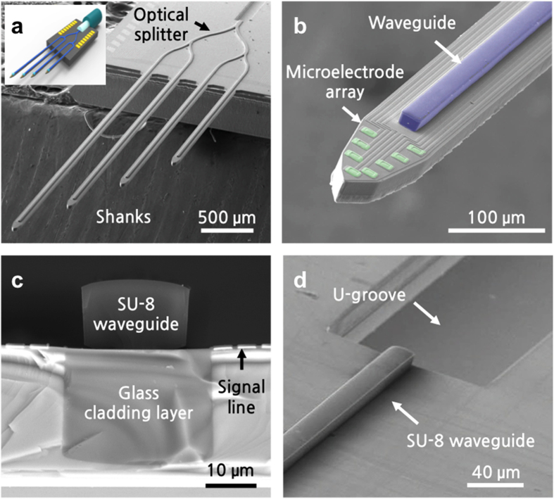
Figure 2. SEM images of the fabricated optrodes.
(a) Bird’s eye view of multi-shank optrode array with an inset showing the conceptual diagram. (b) Tip of a single shank showing the optical waveguide core and microelectrode array. (c) Cross-section of the shank showing the embedded glass cladding and SU-8 waveguide core layers. (d) U-groove to assist alignment of optical fibre to the SU-8 waveguide core.

