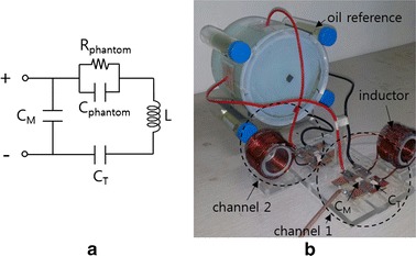
Fig. 5.

Impedance matching of the phantom circuit. a A circuit diagram of the impedance matching circuit and b a photography of the impedance matching circuit connected with the phantom. An external inductance L and two external capacitors, CT and CM, are connected with the phantom circuit modeled by a parallel circuit of Cphantom and Rphantom
