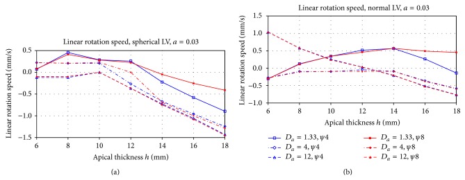
Figure 6.

Residual circumferential speed of the drifting filament after stabilization at the attractors ψ = ψ ∗ shown in Figure 5 for the cases of the spherical (a) and the normal LV shape (b). The X-axis is the apical thickness h, the Y-axis is the speed, mm/s. Different lines correspond to different anisotropy ratios.
