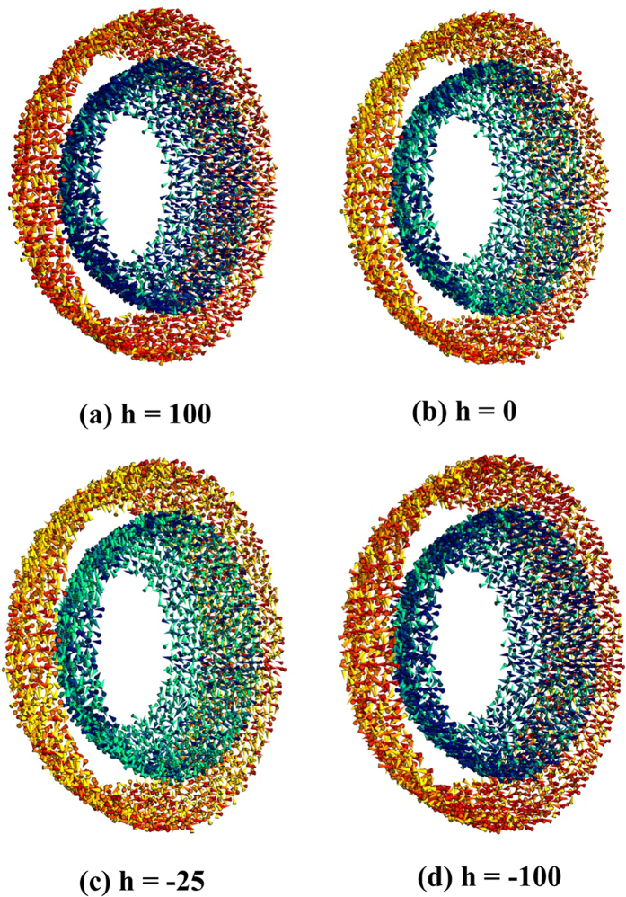
Figure 8.
Snapshots of the outer and inner surface spin configurations subject to varying magnetic fields (a) h = 100 (the maximum positive applied field), (b) h = 0 (remanence at the upper branch), (c) h = −25 (near the negative coercive field), and (d) h = −100 (the maximum negative applied field). Spins have been colored with a gradient from dark-red/dark-blue (outer/inner surface) for spins along the field direction to yellow/green (outer/inner surface) for spins transverse to the field direction. Only a slice of the spin configurations of a hollow nanoparticle close to the central plane and perpendicular to the field direction is shown.

