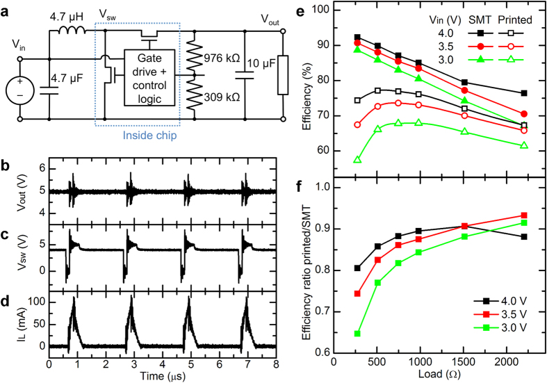
Figure 6.
(a) Diagram of voltage regulator circuit. (b–d) Waveforms of (b) Vout, (c) Vsw and (d) current into the inductor, with 4.0 V input voltage and 1 kΩ load resistance, measured using printed inductor. Surface-mount resistors and capacitors were used for this measurement. (e) Efficiency of a voltage regulator circuit using all surface-mount components vs. one with printed inductor and resistors, for various load resistances and input voltages. (f) Ratio of efficiencies of the surface-mount and printed circuits shown in (e).

