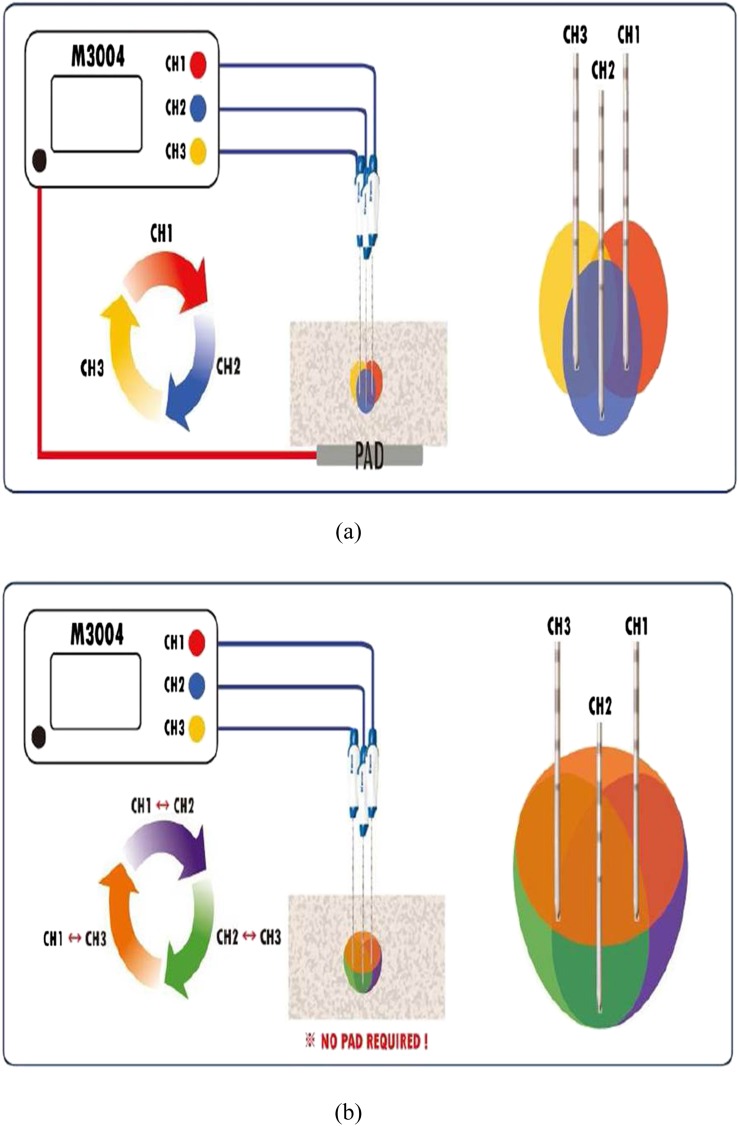
Figure 2.
Diagrams showing the radiofrequency (RF) energy delivery protocol in switching monopolar (SM) mode and switching bipolar (SB) mode. (a) In SM mode, RF energy was applied to one of the three internally cooled wet (ICW) electrodes, and RF energy delivery was automatically changed among the three electrodes depending on impedance changes. (b) In SB mode, RF energy was applied to a pair of the three ICW electrodes, and according to impedance changes, RF energy delivery was automatically changed between the three pairs of three electrodes. Note that there is no grounding pad in RF current circuitry. CH, change.

