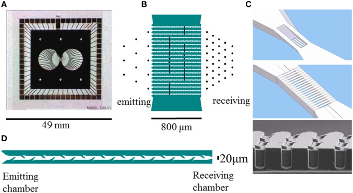
Figure 1.
Layout of the culturing chambers, channels, and electrodes of glass-silicon DCMEAs. (A) shows the complete DCMEA, (B) depicts the layout of electrodes (black lines and dots, Ø: 30 μm) and channels (green). (C) shows a top and bottom view of the connecting channels. The barbed channels are 5 μm high at the entrance and exit, and the central part of the channels has no ceiling to enable visual access. Total channel length: 800 μm, channels, and walls running from lower left to upper right are indicated in (B) in white and green, respectively. Bottom image shows an electron microscopy image of the barbs in the channels. (D) Close-up of a channel (10 barbs per side, length:800 μm, width: 20 μm, all dimensions are to scale). Glass PDMS DCMEAs had a similar layout, but the channels were shorter (540 μm, five barbs per side).

