
Figure 3.
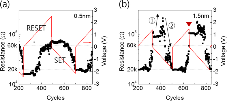
Feedback-loop pulse measurements of (a) Ta2O5 (0.5 nm) device and (b) Ta2O5 (1.5 nm) device. The red lines indicate the write (SET/RESET) voltage and the black dots represent resistance of devices. The dashed line has been added to show the setting values (20 kΩ, 60 kΩ).