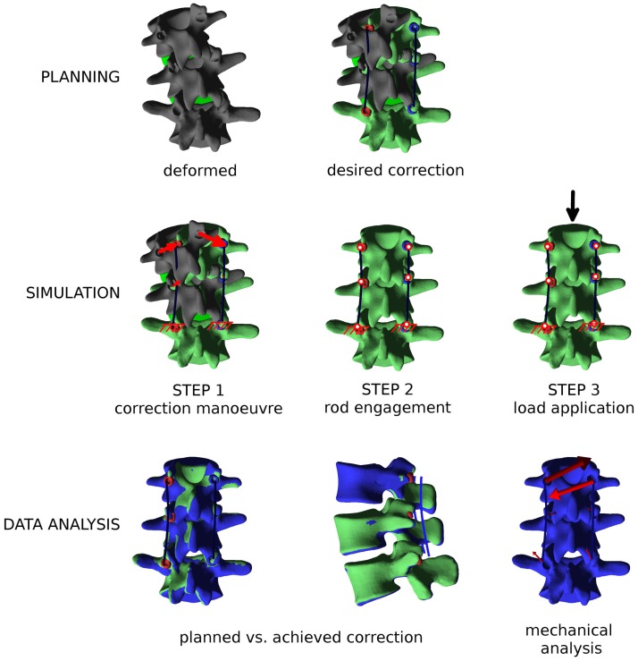
Figure 6.
Overview of the workflow to perform a biomechanical investigation of a spine deformity correction. First (“PLANNING”), the three-dimensional correction is planned as desired with the graphical user interface, and posterior rods with appropriate contours are generated. Then (“SIMULATION”), the finite element simulation is performed in three steps: (i) the correction maneuver; (ii) rods and pedicle screws are locked together; and (iii) external loads are applied, if desired. Finally (“DATA ANALYSIS”), relevant mechanical outputs are extracted from the simulation and analyzed.

