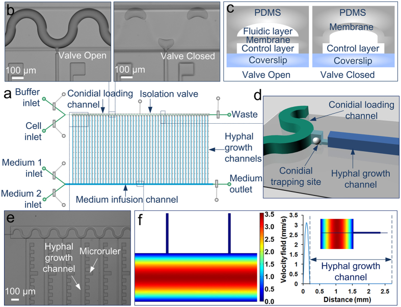
Figure 1. Microfluidic channel array for analyzing hyphal growth and dynamics.
(a) Schematic of the chip layout comprising two layers of channels: a fluidic layer (green, light blue, and blue) and a control layer (grey) with 7 pneumatic microvalves. The fluidic layer consists of four inlets to deliver buffer, cells, and two types of medium, respectively, two outlets, a conidial loading channel (green), a medium infusion channel (blue), and 50 hyphal growth channels (blue) arrayed in parallel. (b) Image of the serpentine conidial loading channel precisely aligned with the isolation valve. The closure of the valve can compartmentalize each growth channel. Scale bar, 100 μm. (c) Schematic of the cross section of a valve. The fluidic channels having rounded cross sections (green) are completely closed when the valves are actuated. (d) Schematic of a conidial trapping site containing two short channels (light blue) with different dimensions and connecting the conidial loading channel (green) and the hyphal growth channel (blue). A single conidium could be captured by the constricted shallow channel. (e) A micrograph showing the channels and the microrulers at the right side of the hyphal growth channels. Scale bar, 100 μm. (f) Numerical simulation of flow profiles in the channels using COMSOL Multiphysics software. The right panel shows the velocity along the cross line from the bottom of the medium infusion channel to the top of the hyphal growth channel (as inset). No flow is present in the hyphal growth channels.

