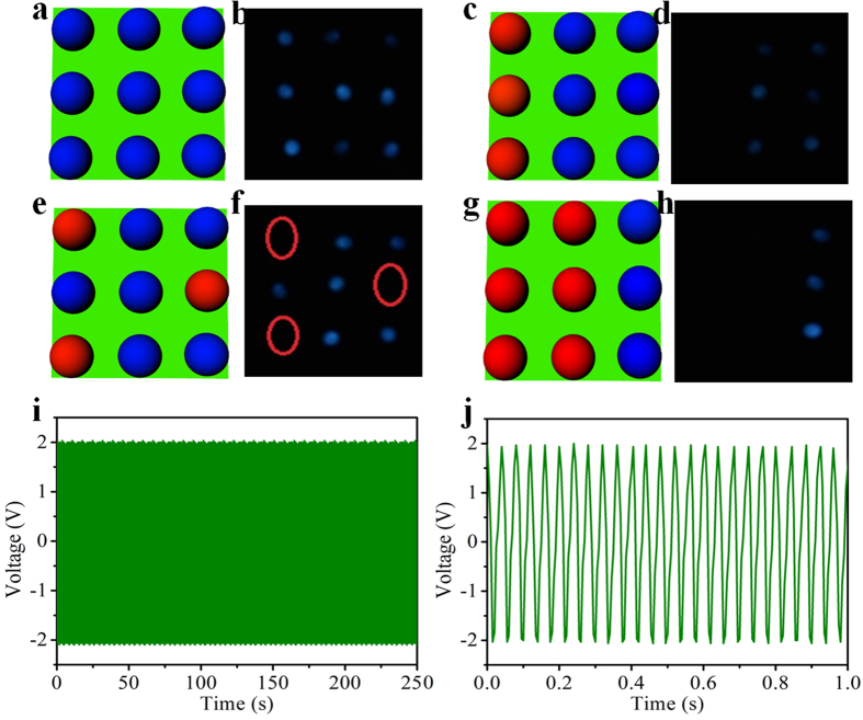
Figure 6. Intuitively illustrates working condition of nine units with LEDs as indicators.
(a,c,e,g) The schematic diagram that every LED is connected with one pixel in the matrix. (b,d,f,h) The snapshots that different amount of LEDs connected to the sensor system extinguished. (e–f) The stability test of the self-powered sensor system. Photograph taken by Qijie Liang.

