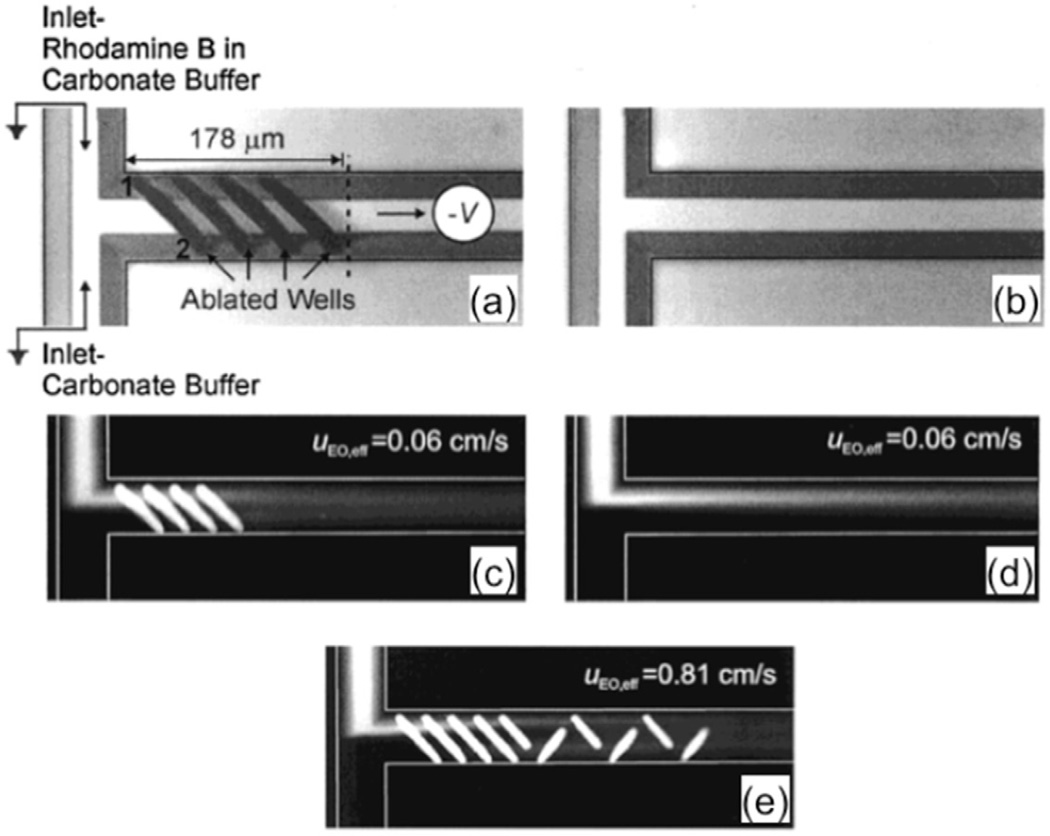
Figure 2.
(a) Configuration of the experimental setup and image of a channel with a series of slanted wells. (b) Image of a smooth channel. (c), (d) Fluorescence image of electroosmotic flow of the corresponding channels in (a) and (b). (e) Fluorescence image for electroosmotic flow past an optimized mixer at a high flow rate (0.81 cm s−1). These figures are adapted from [37] with permission.

