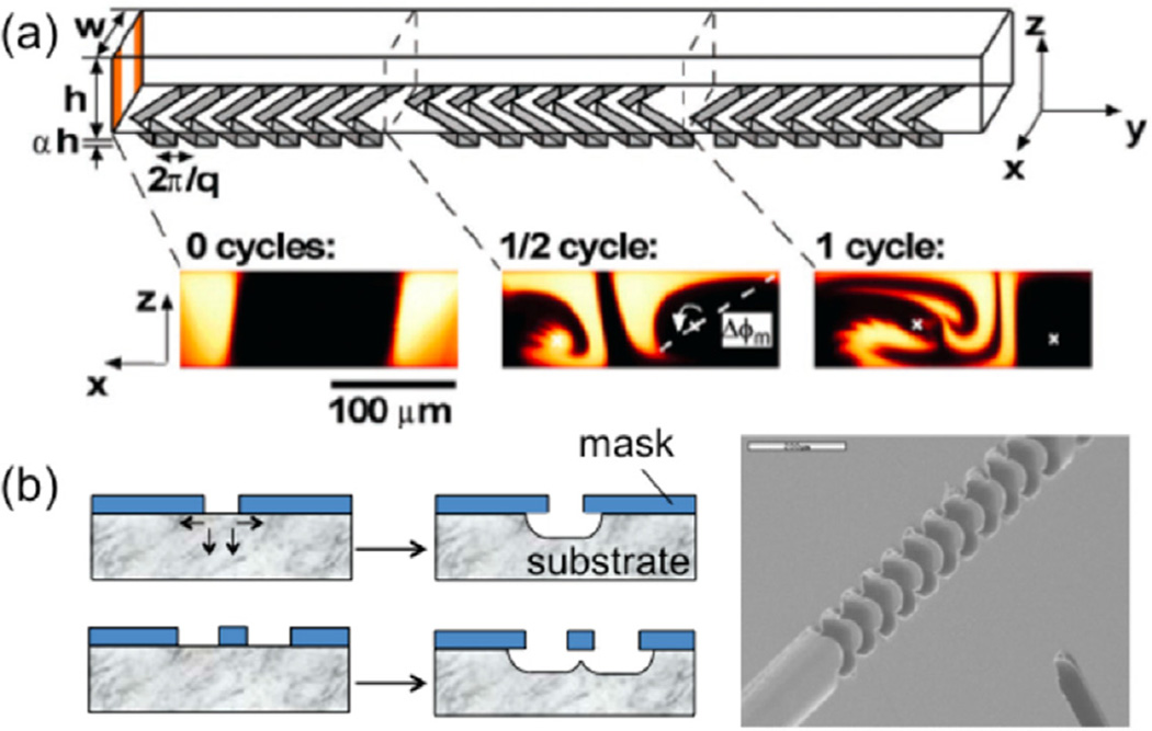
Figure 3.
(a) Schematic diagram of one-and-a-half cycles of the SHM. A mixing cycle is composed of two sequential regions of ridges; the direction of asymmetry of the herringbones switches with respect to the centerline of the channel from one region to the next. At the bottom are confocal micrographs of vertical cross sections of a channel (from [7]. Reprinted with permission from AAAS). (b) (left) Illustration of isotropic etching and ridges obtained from judicious designs and isotropic etching; (right) SEM picture of a ridged channel in a microfluidic device made from a cyclic olefin copolymer. The scaling bar is 200 µm (adapted with permission from [42]. Copyright 2007 American Chemical Society).

