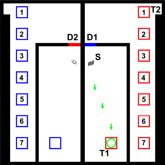
Figure 1. Layout of virtual environment.

We show the start of the training phase with the computer-controlled pedestrian (shown in white) and the participant-controlled pedestrian (shown in grey) located in the central rooms of the left and right hand halves of the building, respectively. The participant-controlled pedestrian is at the starting position, S. Moving pedestrians have animated legs that are not visible when pedestrians are stationary (compare participant-controlled and computer-controlled pedestrians). Green arrows indicate the direction towards the first target, T1 that coincides with a coloured square that can be used for opening door D2 (arrows disappear when T1 is reached). The computer-controlled pedestrian can open door D1 by standing on one of the blue squares in the left hand half of the building. The final exit from the building for the participant is labelled ‘T2’. We show all 7 possible locations for the coloured square in the corridor (labelled 1–7). In the experiment, only one square at one of these locations was shown and we showed squares at the same location in both halves of the building. For the computer-controlled pedestrian to escape, the human participant must stand still on the red square in the corridor on their side of the building. By varying the location of this red square we can test how the perceived relative cost affects helping behaviour.
