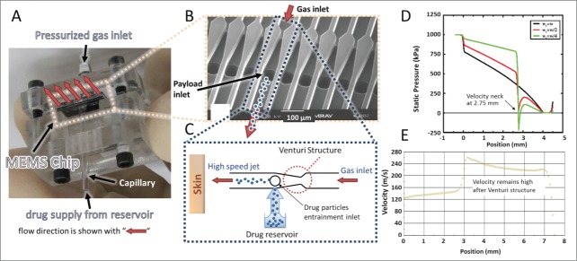
Figure 1.
MEMS device with parallel microchannel arrays and device working principle. (A) MEMS device assembled in a prototype test cell with gas and payload inlets. (B) Scanning electron microscope (SEM) image of the fabricated device showing the parallel channels with Venturi structure and inlet of therapeutic particles. (C) Schematic illustration of operation for one channel. Pressurized gas is supplied to the inlet of the channel and accelerated after the Venturi constriction followed by particle entrainment using the mild suction generated by a brief gas pressure drop. (D) CFD simulation of pressure profile for different widths wt of the Venturi neck (wt = w, wt = w/2, and wt = w/4 where w is the channel width) along a 4 mm long channel with a cross section of 64 × 64 μm2. (E) CFD simulation of velocity profile along a 6.5 mm long channel with a cross-section of 600 × 600 μm2. Simulations in D and E used air as the pressurized gas and did not include particles.

