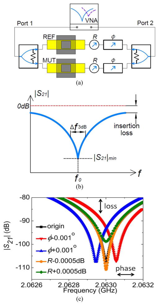
Fig. 1.
(a) Schematic of a power-divider-based RF interferometer, which includes a network analyzer for probing signal generation and detection. The yellow rectangles indicate TLs. (b) Diagram of transmission scattering parameter |S21| indicating the operating frequency f0. (c) Tuning of sensor sensitivity with R and operating frequency with Φ in (a).

