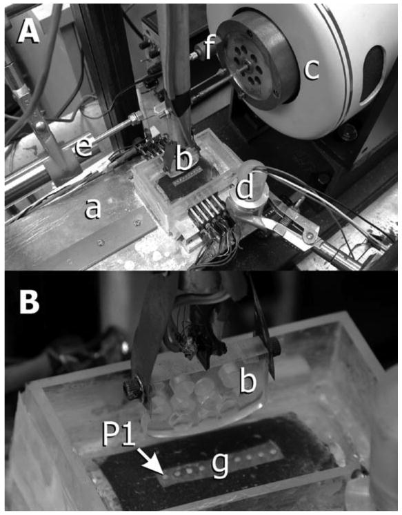
Figure 2.

Equipment (modified from previously published work; Nickel et al., 2004). A: Loading beam: a hinged beam facilitated placement of a static load at one end of the beam, which caused the acrylic indenter to load the TMJ disc at the other end of the beam. During experiments, the disc was supported by a curved acrylic base and tray. B: Indenter: the acrylic indenter had a major radius of 125 mm and a minor radius of 31 mm, polished loading surfaces, and milled holes to reduce the effect of mass on tractional forces measurements. The indenter was connected to a pendulum by an instrumented steel strut. Strain gauges attached to the surfaces of the strut (see B) measured bending of the strut during movement of the indenter over the surface of the cartilage. Tractional forces were measured in real time via calibration of output voltages from gauges for given loads. C: Electromagnetic force generator: a computer and custom-built software controlled the position and velocity of force generator displacement. D: Linear voltage differential transformer used to measure cartilage thickness during translation of the indenter over the surface of the disc. E: Linear voltage differential transformer used to measure real-time horizontal position of the indenter relative to the disc. F: Accelerometer: output of the accelerometer was used to identify the start of movement of the indenter across the mediolateral axis of the disc. G: Pressure sensitive array: an array of transducers lined the inside of the loading tray and measured pressure along the mediolateral axis of the disc. The most medial portion of the disc was positioned over pressure transducer #1 or #9.
