
Figure 6.
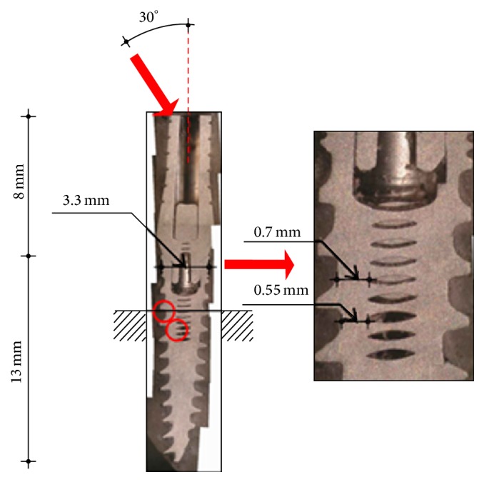
Metallographic section from in vitro fatigue testing of 3.3 mm implant diameter. The length and width of the implant and abutment are indicated. The upper red arrow indicates testing force applied to the implant abutment and the force direction at an angle of 30° off-axis. The red circles indicate the different fracture location found for this implant diameter. The magnified picture shows the fracture location and the corresponding metal width at the fracture location. Reprinted with permission from [46].