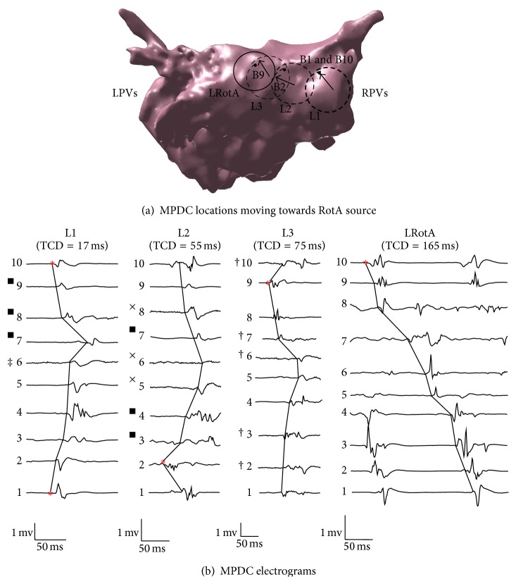
Figure 7.
Clinical study, Path B: (a) The dashed rings (L1, L2 and L3) are the location of MPDCs moving towards the RotA represented by a solid ring (LRotA); the first activated bipole is denoted by the corresponding bipole number and an arrow pointing to it. The solid ring indicates the location of the MPDC recording that encompasses the rotor source. ∗ represents bipole 1 of each MPDC. (b) A single cycle from the electrograms obtained at each of L1, L2, L3, and LRotA is shown along with the corresponding TCD reported at the top of each electrogram; the first activated bipole is indicated by the asterisks; the corresponding bipole electrode numbers 1 through 10 are indicated beside every bipole. RPVs: right pulmonary veins; LPVs: left pulmonary veins. ■ Voltage scaling decreased 2×. † Voltage scaling decreased 4×. ‡ Voltage scaling decreased 5×. × Voltage scaling decreased 6×.

