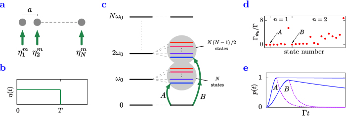
Figure 1. Selective state preparation procedure.
(a) A chain of  closely spaced quantum emitters (separation
  with
with  ,
,  being the laser wave number) are individually driven with a set of pumps
  . (b) The lasers are turned on for a time
  , optimized such that an effective
  -pulse into the desired subradiant target state is achieved. (c) Level structure for the
  systems where the
  -fold degeneracy of a given
  -excitation manifold is lifted by the dipole-dipole interactions. The target states are then reached by energy resolution (adjusting the laser frequency) and symmetry (choosing the proper
  ). (d) Scaling of the decay rates of energetically ordered collective states starting from the ground state (state index
  ) up to the single- and double-excitation manifolds for
  particles at a distance of a = 0.02λ0. The arrows identify the decay rates for the lowest energy states in the single (A) and double (B) excitation manifolds. (e) Numerical results of the time evolution of the target state population for N = 6 and a = 0.02 λ0 during and after the excitation pulse. Near unity population is achieved for both example states A (where we used η = 0.53 Γ) and B (for η = 2.44 Γ) followed by a subradiant evolution after the pulse time
  shown in contrast to the independent decay with a rate
  (dashed line).

