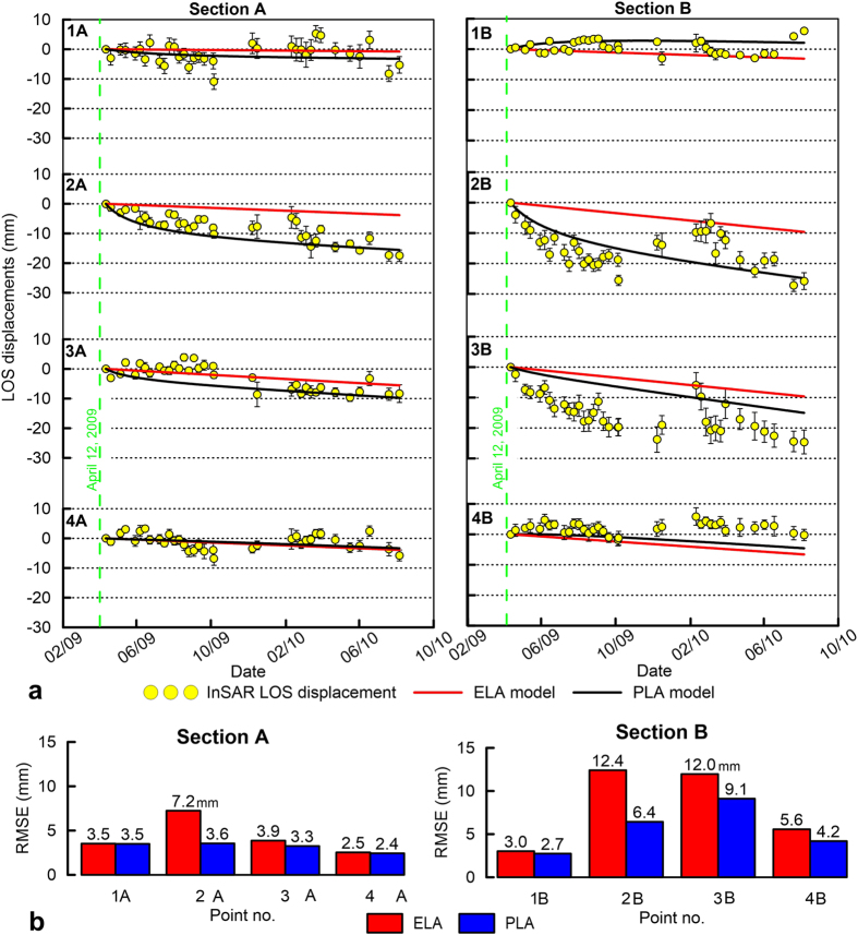
Figure 5.
(a) Time series of the observed (yellow circles) and modelled (red and black lines) LOS displacement time series for points on sections A and B in Fig. 3a. The black line represents the PLA model results, and the red line represents the ELA model results. The error bars refer to the standard deviation among the point scatterers inside a circular area with a 100 m radius. (b) RMSE between observed and modelled displacements for the ELA and PLA models. Figures were created with Golden Software Grapher.

