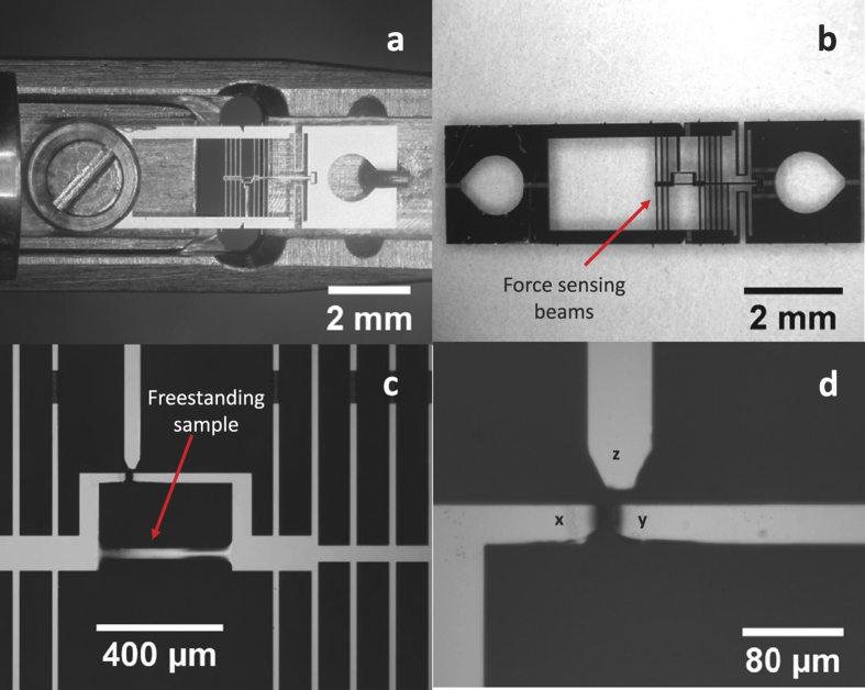
Figure 1. MEMS device and experimental setup:
(a) Optical micrograph of a typical MEMS device mounted on the TEM straining holder. (b) Optical micrograph of the MEMS device showing the force sensing beams. (c) Optical micrograph showing the freestanding Al sample and the strain and force measuring gauges. (d) Zoomed in image of the two strain sensing gauges x and y and the stationary force sensing gauge, z. The change in distance between gauges x and y gives the deformation on the sample while the change in distance between gauges x and z multiplied by the stiffness of the force sensing beams gives the force acting on the sample.

