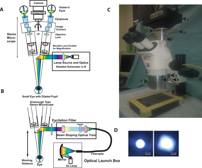
Figure 1.
Schematic diagram of the major components of the on-axis retinal imaging platform. (A) An intense small gap continuous xenon source is collected and condensed into a small core diameter fiber optic with approximately matching numerical aperture. The fiber leaves the launch box and is coupled into the Greenough type stereo microscope exploiting the open optical “space” (∼10°) between the two stereo viewing axes. The cone of light emerging from the fiber is collected, shaped, and condensed into a beam focus by an optical train of three achromatic lenses (two fixed positive lenses and one mobile negative lens) with the focal point approximately 7.5 cm from the last optical component in the system. The narrow condensed beam is folded onto the optical axis of the microscope by a tiny front surface mirror or prism that can be used to steer the beam. The beam condenses into the small dilated pupil of the mouse eye in a Maxwellian imaging paradigm. The mouse and eye are positioned to match this point in space for maximal coupling. The eye is visualized with a stereo imaging system and a camera is attached for photodocumentation. Excitation and emission filters are appropriately placed to modulate the input and output beams. (B) Optical schematic of the fiber optic launch box (Welch Allyn, CL-100) and the optical delivery train at the level of the microscope. The short arc xenon source with an NA 0.52 is coupled into a matched high NA fiber with a spherical mirror positioned proximate to the xenon lamp, which is held in a vertical position. The fiberoptic transmits the energy to the stereo microscope, initially orthogonal to the optical axis. An optical rail made from three achromatic lenses collects the energy from the fiber into an approximately collimated beam, shapes the angle of the beam (with the moveable negative achromatic lens), and condenses the beam into the specimen plane. The position of the fiber relative to the first positive achromatic lens shapes the collimation of the beam. The final positive lens focuses the energy onto the specimen plane. An excitation filter modulates the spectral pattern of the beam. A 45° mirror directs the beam onto the optical axis, which resides between the independent stereo imaging axes. (C) Image of the Zeiss Stemi 2000-C microscope modifications for the RIS converting it to the brightfield, far-red, and fluorescence setup. The components include the: fiber optic cable entry point (a), the fiber optic holder (b), the optical elements holder (c), the spot size regulator (d), the microscope body (e), the microscope/camera coupling spacer with emission filter rail (f), the adjustable z-axis camera mounting ring (g), the emission filter rail (four filters) (h), the SPOT Flex camera (i), and the excitation filter rail (j) (the CL-100 light source is not shown). (D) Spot sizes in the mouse pupil plane. Image of the minimum (left) and maximum (right) spot sizes created with a 1.4-mm core fiber input. Images were taken with the beam focused onto a flat optical surface placed at the focal point of the eye input beam. The spot size is controlled by moving the position of the negative beam shaping lens in the optical train. Scale bars: is 1.0 mm.

