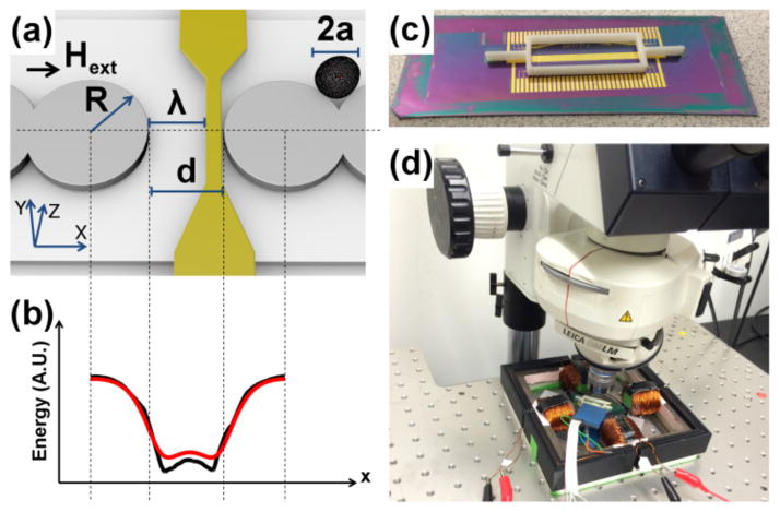
Figure 1. Illustration of the transistor geometry and potential energy distribution.
(a) Ni81Fe19 permalloy disks (gray circles) of radius, R, and thickness, τm are designed with a small gap of distance, d. A gate electrode (gold wire) is overlaid with its left edge shifted from the opposing gap side by a distance, λ. A magnetized cell (black circle) of radius, a, is shown moving along the magnetic track. The external field direction, Hext, is aligned along the track axis, depicted as the black arrow. The potential energy line cross-section simulated at a vertical height of z = a is shown in (b) from finite element (FEM) analysis (black line), and from analytical charge model (red line) based on Eqs. 1–2. A photograph of the chip and 3D printed container used to test the transistors are shown in (c). The overall instrument apparatus is shown in (d).

