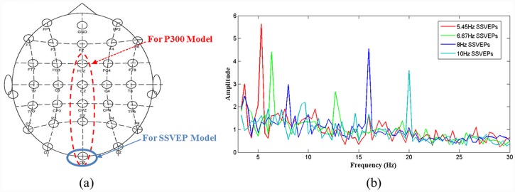
Fig 3. Electrode placement and SSVEP signal spectrum.
(a) EEG electrodes placed in accordance with the International 10–20 system. The electrode circled with a blue solid line is the channel in which brainwaves are induced by the SSVEP model, and the electrodes circled with a red dashed line are the prominent channels among which the most responsive channel is selected to acquire the brainwaves induced by the P300 model. (b) SSVEP power spectrum of subject subj1 acquired from channel Oz when the subject was staring at flickering targets modulated at four frequencies.

