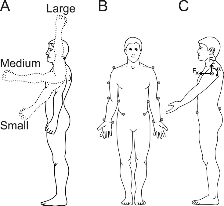
Fig 1. The experimental set-up.
In (A) the three different arm movement amplitudes are illustrated with the solid arm showing the start position of all movements and the three dashed arms representing the three different end positions. In (B) and (C), the marker positions used are shown and in (C) also the reactive torque (α) on the trunk around the centre of rotation and the linear forces in the antereo-posterior (Fx) and caudo-cranial (Fz) directions during the deceleration of an arm movement is illustrated.

