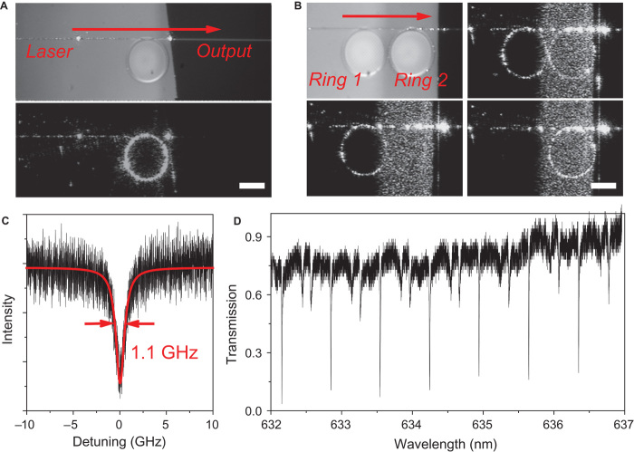
Fig. 2. Characterization of printed microrings as high-Q resonators.
(A) Microscopy image of the structure built for optical measurement. (Top) The optical fiber taper was coupled with a microring at the edge of the film, which was connected to a wavelength-tunable laser at one end and to a photodetector at the other end. (Bottom) The microring was uniformly illuminated when the input wavelength was found at any of its resonance modes. Scale bar, 50 μm. (B) Microscopy image of two conjugated microrings coupled with the fiber taper (top left). The incident laser was tuned to the wavelength of the resonance mode of ring 1 and/or ring 2 to illuminate the rings simultaneously (top right) or separately (bottom). Scale bar, 50 μm. (C) Frequency detuning profile of the 632.15-nm (~4.75 × 10⁵ GHz) resonance mode from the microring resonator with a TE polarized laser. The corresponding Q factor is 4.33 × 10⁵, as calculated from the frequency of incident light divided by the linewidth of the Lorentz fit (red). (D) Broad-range transmission spectrum from the microring, where periodic sharp dips indicate an average Q factor higher than 105.

