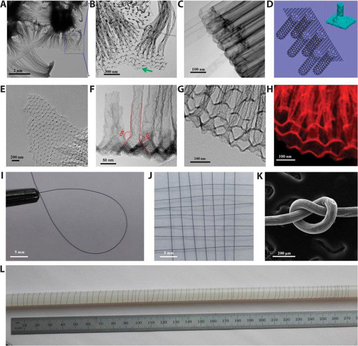
Fig. 2. Microscopy characterization of the 3D graphene-RACNT structures.

(A and B) Graphene sheet connecting to the open tips of RACNTs. (C) Closed end of RACNTs. (D) Schematic representation of the 3D graphene-RACNT network; inset shows the energy-minimized structure from MD simulations (Supplementary Materials). (E) Broken graphene sheet from the 3D graphene-RACNT network. (F) TEM image of the side view of the 3D graphene-RACNT around the graphene-nanotube interface. (G and H) Cross-section view of the constituent RACNTs within the 3D graphene-RACNT structure (G) and corresponding carbon mapping (H). (I) Circle-shaped 3D graphene-RACNT fiber. (J) Piece of weaved graphene-RACNT fibers. (K) SEM image of a knot of the graphene-RACNT fiber. (L) Photograph of a 2-m-long graphene-RACNT fiber rolled on a long stick. [The diameter of the graphene-RACNT fibers in (I) to (L) is 100 μm.]
