
Fig. 1. Experimental setup.
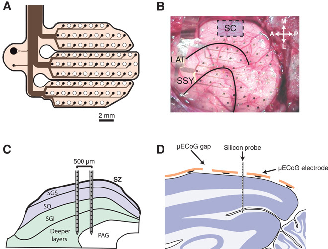
(A) Schematic diagram of the custom-designed μECoG array. Sixty-four electrodes of 250-μm diameter were distributed across three separate polyimide fingers and arranged in a hexagonal grid (1.5-mm inter-electrode spacing). Holes were cut into the polyimide foils in the space between electrodes to allow for the placement of linear silicon probes. (B) A photo from the surgical implantation of the μECoG array. The general area for SC penetrations is shown by a blue box. Black lines indicate the lateral sulcus (LAT) and the suprasylvian sulcus (SSY). (C) Schematic diagram illustrating the placement of dual-shank 32-channel silicon probes in the SC. Probes were placed such that neural data could be acquired from both superficial (blue) and deep (green) layers of the SC simultaneously. (D) Schematic illustration of the placement of linear silicon probes in the visual cortex. Single-shank 32-channel probes (100-μm inter-electrode spacing) were advanced into the cortex through small holes in the μECoG array. Probes were advanced until the most superficial contacts were just above the pial surface, such that we recorded, in a single penetration, from superficial and deep visual cortex simultaneously. SZ, stratum zonale; SGS, stratum griseum superficiale; SO, stratum opticum; SGI, stratum griseum intermediale; PAG, periaqueductal gray.