Figure S1.
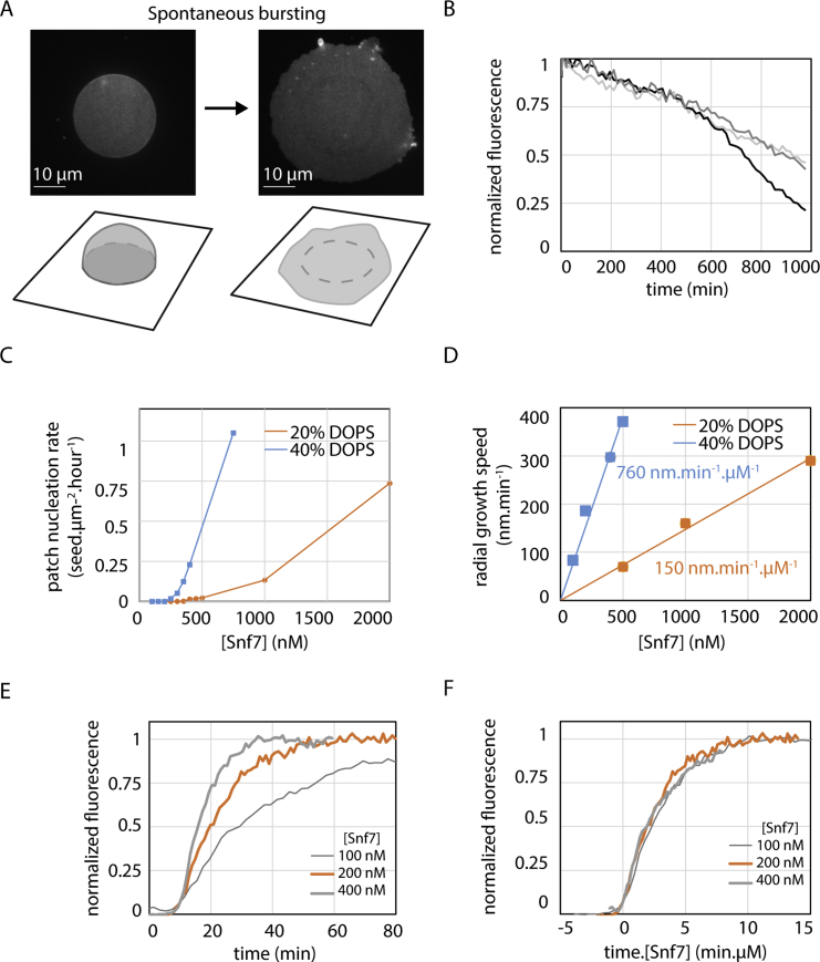
Dynamics of Snf7 Patches on Supported Membranes, Related to Figure 1
(A) GUV bursting on glass coverslip. Left: GUV before bursting. A strongly adhered GUV, labeled with Rhodamine-PE, is visualized by spinning-disk confocal microscopy. The focus is made on the bottom of the vesicle, showing the circular patch of adhesion. Below is the 3D sketch showing the strongly adhered vesicle. Right: Same vesicle shortly after bursting occurred and corresponding sketch. See also Movie S1. (B) Spontaneous Snf7 patch depolymerization after Snf7 washout in solution. The curves represent different locations where depolymerization is measured. See also Movie S3. (C) Patch nucleation rate as a function of [Snf7] for a DOPC 60% / DOPS 40% membrane (blue curve) and for a DOPC 80% / DOPS 20% membrane (orange curve). (D) Patch radial growth speed as a function of [Snf7] for a DOPC 60% / DOPS 40% membrane (blue curve) and for a DOPC 80% / DOPS 20% membrane (orange curve). Lines are linear fit with the slope equals to 760 nm.min−1.μM−1 (blue) and 150 nm.min−1.μM−1 (orange). (E) Fluorescence intensity curve (average of 5 patches) with time at a given point on the membrane upon coverage by a Snf7 patch, for [Snf7] = 100 nM (thin gray line), 200 nM (orange line), 400 nM (thick gray line). (F) Same curves as (E) plotted as a function of time multiplied by Snf7 concentration in μM. All graphs merge on one single master curve, revealing that the coverage dynamics is proportional to Snf7 bulk concentration.

