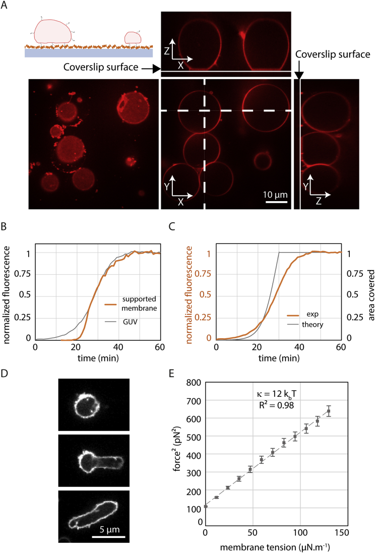
Figure S5.
Using GUVs to Study Snf7 Mechanics, Related to Figure 5
(A) Partially adhered GUVs within a flow chamber. Top left: experimental setup to follow partially adhered vesicles within a flow chamber. A coverslip (blue-gray) is coated with avidin (orange) by adsorption. GUVs (red) containing peg-biotin lipids (black arrows) are flowed within the chamber and attach to the glass surface. Passivation of the surface is then made by flowing biotinylated bsa, allowing to keep for long time partially adhered vesicles. Bottom left: GUVs images taken at the coverslip surface showing the adhesion patch of vesicles. Bottom middle: equatorial section of GUVs. Side images: Y-Z and X-Z sections (dashed line) reconstructed from Z optical sections. (B) Comparison between patch coverage dynamics and GUV coverage dynamics. Gray: dynamics equals to the average of 4 GUVs shown Figure 5C. Orange: equivalent to graphs shown Figure S1E for [Snf7] = 500 nM. The initial dynamics is steeper for Snf7 patches but the saturation dynamics is similar. (C) Comparison of the dynamics of surface coverage between GUVs experiments and the mathematical modeling. Orange: dynamics equals to the average of 4 GUVs shown Figure 5C. Gray: result of the mathematical modeling for [Snf7] = 500 nM ( = 40 nm2.s−1 and λ = 8.2 × 10⁻³ spiral.μm−1.s−1). (D) Plastic behavior of strongly coated vesicle, another example of Figure 5E. A round shaped vesicle is being held gently by a pipette (left), then a suction pressure is exerted (middle) to deform the vesicle. Upon pressure release (right), the vesicle keeps the shape of the pipette. (E) Membrane bending rigidity (κ) measurement of a DOPC 60% / DOPS 40% vesicle. Plot of the tether force squared as a function of experimentally imposed membrane tension for the vesicle shown in Figure 5H and 5I. The variation is linear with an expected slope of 8π2κ. The linear fit yields the bending rigidity J.

