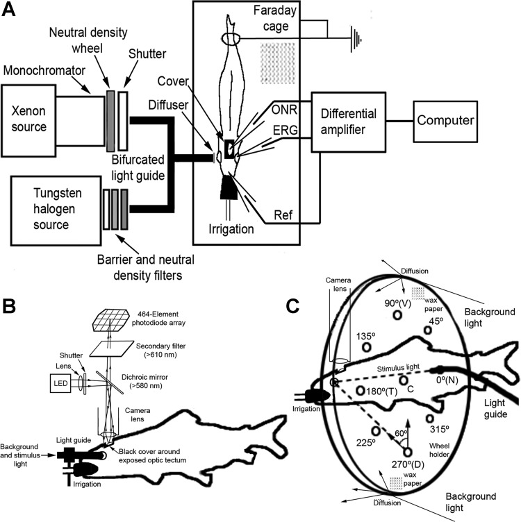
Fig. 1.
Diagrams showing main features of setup for electrical and optical recordings. A: schematic of the 2 optical channels: stimulus (Xenon source) and background (tungsten/halogen source), converging onto the common end of a bifurcated light guide with a diffuser at its extremity. Light from the guide illuminates the fish's eye, and electrical or optical recordings of retinal activity are acquired using electrodes or a voltage-sensitive dye (VSD) and photodiode array system. Differential recordings of electrical activity between the optic nerve [optic nerve response (ONR)] or the retina [electroretinogram (ERG)] and a reference (Ref) electrode are amplified and analyzed by computer. B: for optical recordings, a photodiode array system was positioned above the exposed optic tectum to acquire fluorescence signals. LED, light-emitting diode. C: modification of the stimulus and background illumination using a diffusive acrylic wheel equipped with holes for light-guide insertion. Except for the center (C) hole, which approached alignment with the normal to the center of the iris, the other holes were directed at 60° to the center of the iris. The holes were placed every 45° around the trigonometric circle, with 0° illuminating the nasal (N), 90° the ventral (V), 180° the temporal (T), and 270° the dorsal (D) retina.

