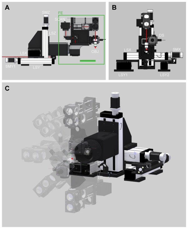
Fig. 1.
Mechanical design. (A) Side view of the microscope. Green line indicates 193 mm space behind objective (OBJ). (B) Front view of the microscope. (C) 3D view showing the rotational freedom of microscope frontend (FE). Linear stage for X axis (LSX), linear stage one and two for Y axis (LSY1 and LSY2), linear stage for Z axis (LSZ), stepper motors (SMX, SMY1, SMY2, SMZ, SMR (not shown)), detection system (DS), objective (OBJ), and mounting block for scanners (SCAN). Focal point of OBJ is highlighted with a red dot.

