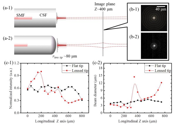
Fig. 3.
The schematic diagram of two types of AFBG and their beams propagation in the air: (a-1) Flat tip type (advanced one) and (a-2) Lensed tip type (prior one). The cross section images of the beam from AFBGs with the flat tip (b-1) and the lensed tip (b-2) taken by a CCD camera at the propagation distance of 400 μm from fiber tip. The longitudinal (c-1) and transverse (c-2) intensity profiles of beams from AFBGs with flat tip (black) and lensed tip (red).

