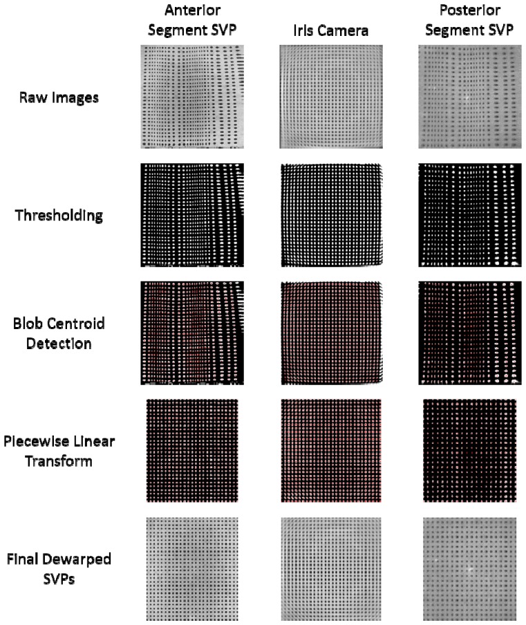
Fig. 6.
Distortion correction. (top) Raw images of the grid target were thresholded (upper middle) and the blob centroids (shown in red) were automatically detected (middle). The dot locations were used to create a least-squares piecewise linear transform to dewarp the image as shown by the thresholded (lower middle) and final dewarped images (bottom). The left, center and right columns indicate images acquired in the anterior, iris camera, and posterior segment imaging modes, respectively.

