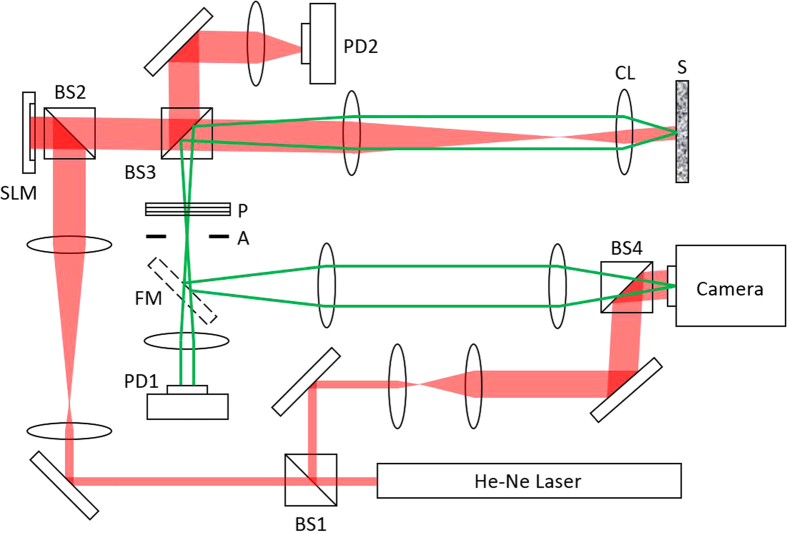
Figure 2. Schematic diagram of experimental setup.
He-Ne Laser (Melles Griot 25-LHP-928–230), BS1-4: Beamsplitters, SLM: Spatial Light Modulator (Hamamatsu Photonics, X10468–06), PD1 and PD2: photodiodes (THORLABS, PDA36A–EC), S: disordered medium, CL: condenser lens (Nikon, Achr-Apl N.A = 1.4), FM: flip mirror, Camera (RedLake M3), P: polarizer, and A: aperture. Reflected wave from the disordered medium to the detector sensors was indicated as green lines for clarity although its wavelength is the same as that of incident wave.

