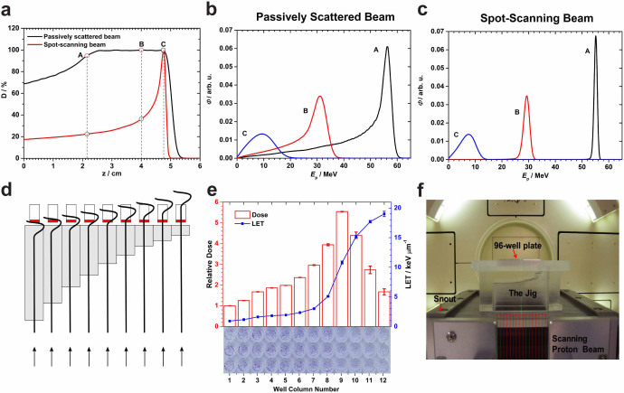
Figure 1. Rationale for using the scanned monoenergetic proton beams for biology experiments and design of the irradiation device.
(a) Depth-dose profiles for a 79.7-MeV scanned proton beam vs. a matched passively scattered beam of the same range with a 3-cm spread-out Bragg peak (SOBP) in water. (b) Energy spectra of protons at three points A, B, C within the scattered beam marked in panel (a). (c) Corresponding energy spectra for the monoenergetic 79.7-MeV scanned beam. (d) Schematic diagram of the irradiation device (jig) concept illustrating the strategy for the column-by-column simultaneous irradiation of biological samples in the 96-well plate with protons at different points on the pristine Bragg curve. Gray bars indicate Lucite; red, culture medium. The stepped construction is designed to match the columns of a 96-well plate and serves to vary position along the Bragg curve, although only 9 columns are shown in the illustration and the step dimensions are not to scale. (e) Dose and LET distributions in the cell layers, positioned atop the jig, were computed using Monte Carlo simulations. The relative dose results shown were normalized to the entrance dose in column 1 in the 96-well plate. The LET shown is dose-averaged LET. The associated errors for both dose and LET were obtained from a sensitivity analysis of experimental setup uncertainties. The thickness of the 12 steps in the jig was selected according to the variations of dose and LET along the Bragg curve. Column 9 was aligned with the Bragg peak by inserting three films of thickness 268 µm each. An exposed and processed 96-well plate is shown at the bottom of the panel to illustrate the dose-LET effect of cell kill. (f) The jig directly mounted onto the scanning beam gantry. The 96-well plates are inserted into a precisely milled slot in the jig holder designed to minimize positioning errors. Protons are incident from below.

