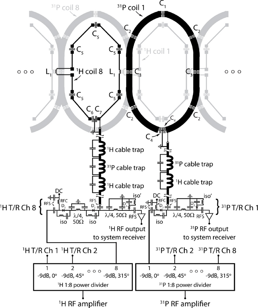
Figure 3.
Flattened two-dimensional schematic diagram of the 31P/1H coil array and interface. For simplicity one 31P and one 1H coil of the 16-channel nested array are highlighted in black while neighboring elements are displayed in light gray. The status of the DC bias is forward in transmit mode and reverse in receive mode. In receive mode, components D1 and iso provide isolation between the RF amplifier and preamplifiers in receive mode, while the iso’ components minimize insertion loss between the coils and preamplifiers. The λ/4, 50Ω circuit help balance the transmit path and improve isolation. Typical component values are; C1 = 40 pF, C2 = 56 pF, C3 = 27 pF, C4 = 75 pF, C5 = 5.3 pF, C6 = 30 pF, C7 = 36 pF, L1 = 24 nH, RFC: radiofrequency choke (1 to 10 uH), and RFS: radiofrequency short (330 to 1000 pF).

