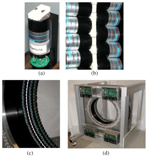
Fig. 1.
Pictures of the Tachyon Camera. (a) A single detector module, with two LSO crystals per PMT and a hole in the top reflector on each crystal. (b) Close-up of the crystal ring. The white region is the crystals covered with white spray paint reflector. The PMTs are on either side axially to couple with the large faces of the crystals. The small faces of the crystals point to the center of the ring. (c) About 20% of the detector ring. (d) Entire camera, also showing the four assemblies of the readout electronics. In order to see the detectors, neither the patient bed, the lead shielding, nor the light covers are installed.

