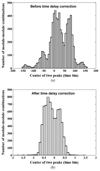
Fig. 6.
Spectra of the center positions of the two peaks (a) before and (b) after the time delay correction. The width of the time bin is 25 ps. Before the time delay correction, the center positions of the two peaks in all valid module-module combinations ranged from about −150 to 150 time bins. (b) After the time delay correction, the center positions range from −1 to 1 time bins with a few outliers. Note that we used floating point numbers in the time delay correction, so most of the residual time delay errors were less than 1 bit (25 ps).

