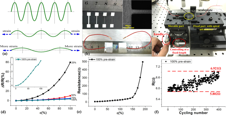
Figure 4. Resistive response characterizations of the wrinkled electrodes.
(a) stretchable schematic diagram to describe the deformation of wrinkles with applied strain; (b) optical image of test structures used and the packaged structures; (c) characterization system; (d) strain induced resistive performances for samples with different pre-strained (25%–100%); (e) strain limitation characterization for the samples with the pre-strain of 100%; (f) the reproducibility characterization by stretching cycle test with the sample of 100% pre-strain.

